- 3D Printing Services

- CNC Machining Services

- Vacuum Casting Services

- Surface Finishing Services




 English
 Español

China 3D Printing Services and CNC Machining Manufacturer Guide
Content
- 1 The Direct Answer: What an Integrated Smart Manufacturing Platform Actually Delivers
- 2 Why Fragmented Sourcing Costs More Than It Appears To
- 3 The Capability Set Behind Professional 3D Printing Services
- 4 Matching Process to Requirement: A Comparison Table
- 5 Large Scale 3D Printing Service: Building Beyond the Standard Envelope
- 6 Custom CNC Machining Services: Where Precision Is Actually Created
- 7 Comparing the Three Core Routes on the Criteria That Matter
- 8 Silicone Mold Replication: The Bridge Between Prototype and Production
- 9 Surface Treatment: The Step That Determines Perceived Quality
- 10 What Work Actually Arrives at a One-Stop Platform
- 11 How to Evaluate a China 3D Printing Services Factory Before You Commit
- 12 The Design-to-Product Workflow on a Single Platform
- 13 About Zhejiang Jiaheng Intelligent Equipment Manufacturing Co., Ltd.
- 14 Industry Applications and Where Each Route Fits
- 15 Preparing Files and Specifications That Get Good Parts Back
- 16 Frequently Asked Questions
The Direct Answer: What an Integrated Smart Manufacturing Platform Actually Delivers
If you are sourcing parts from a China 3D Printing Services Manufacturer, the single most useful thing to know is this: the process route matters less than whether one supplier controls the whole chain from digital file to finished, inspected part. A buyer who sends a model to one vendor for printing, ships the output to a second vendor for machining, and then trucks the parts to a third vendor for painting typically loses seven to twelve working days to handoffs alone, and every handoff is a place where tolerance responsibility becomes ambiguous. An integrated smart manufacturing platform removes those gaps by holding design review, additive manufacturing, subtractive machining, silicone mold replication, surface treatment and dimensional inspection inside one production system with one quality record.
In practical terms, that means a single engineering conversation instead of three, one set of drawings interpreted one way, and one party accountable when a bore comes back 0.05 mm oversize. For engineers evaluating 3D printing service providers, the checklist is short and concrete: can they print in resin, nylon and metal; can they follow the printed part with CNC machining on critical features; can they bridge into small-batch volume without hard tooling; and can they document all of it. A supplier that answers yes to all four is offering one-stop precision manufacturing solutions rather than a single-process job shop.
The rest of this article explains how each capability works, where each one is the right choice, what accuracy and lead time you can realistically expect, and how to evaluate a China CNC Machining Services Manufacturer or a China Industrial 3D Printing Service Supplier before you commit a program to them. Every recommendation below is written for a technical buyer who has to defend the sourcing decision internally.
Why Fragmented Sourcing Costs More Than It Appears To
Most procurement teams compare suppliers on the quoted line item for a single operation. That comparison is incomplete, because the real burden of a fragmented supply chain sits in the spaces between operations: re-quoting, re-fixturing, re-inspection, freight between plants, and the engineering hours spent translating one vendor's assumptions into another vendor's language. A part that requires printing, machining, bead blasting and painting passes through four scheduling queues when it is split across four suppliers, and queue time is almost always longer than process time.
Consolidating with one industrial 3D printing service that also runs machining and finishing lines changes the arithmetic. Fixturing data created for the printed blank is reused for the machining step. Material certificates follow the part instead of arriving separately by email. Non-conformances are caught at the station that created them rather than three weeks later at a downstream vendor. In typical low-volume programs, consolidation reduces total elapsed time from released file to inspected part by 35 to 50 percent, even when the individual process times are unchanged.
Where the days actually go
The chart below compares typical elapsed lead times for common process routes, measured from the moment a manufacturable file is released to the moment parts are packed for shipment. These are working days for a single job in a normally loaded shop, not theoretical minimums.
Several things are worth reading out of this chart rather than skimming past it. First, resin printing is the fastest route to a physical object, which is why a 3d model printing service remains the default for early form and fit reviews where mechanical loading is not yet a concern. Second, metal additive parts and stainless steel machined parts converge at roughly the same lead time, because both are dominated by post-processing rather than by the primary forming step: metal prints need stress relief, support removal and often finish machining, while stainless machining needs slower feeds, more tool changes and deburring. Third, the silicone mold route is the longest single path on the chart, but that number covers fifty finished copies rather than one, so its per-piece time is by far the lowest of the six. Fourth, the gap between aluminium and stainless machining is not a scheduling artifact but a physics one, and any supplier who quotes them as identical has not thought about the job. Finally, none of these figures improve much by choosing a faster machine; they improve by removing the waiting between steps, which is exactly what an integrated platform is designed to do.
The Capability Set Behind Professional 3D Printing Services
The phrase 3D printing services covers a family of processes that share only the idea of building material layer by layer. Their tolerances, surface characteristics, material properties and economic sweet spots differ enormously, and choosing the wrong one is the most common cause of disappointment among first-time buyers. A capable China Custom 3D Printing Service Manufacturer will not simply accept a file and print it on whichever machine is idle; it will ask what the part has to survive, how many are needed, and what happens to the part after it leaves the build chamber.
Resin processes for visual and dimensional fidelity
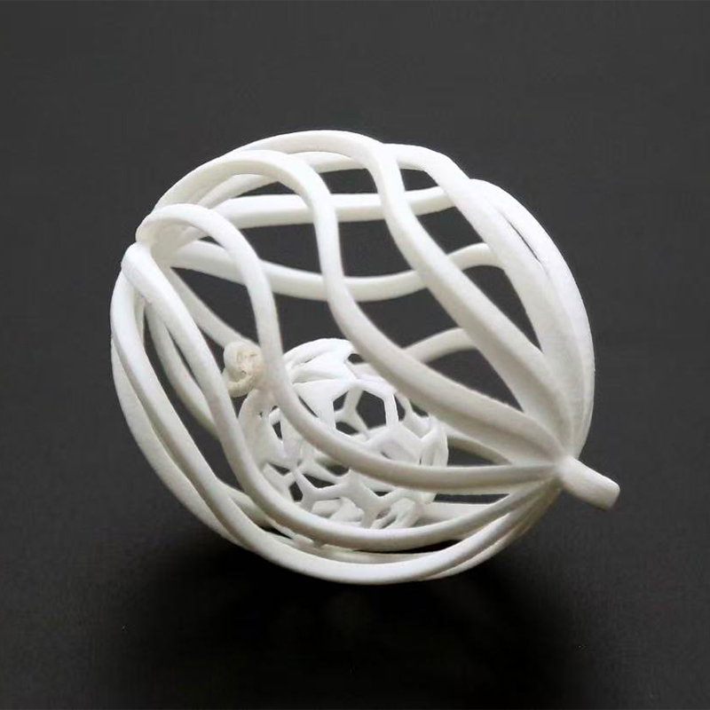
Stereolithography and related resin technologies produce the smoothest as-built surfaces available in additive manufacturing, with layer heights commonly between 0.025 mm and 0.1 mm. That makes them the right tool for appearance models, transparent light guides, fine lattice structures and master patterns destined for silicone molds. The trade-off is mechanical: standard resins are comparatively brittle and lose stiffness when held at elevated temperature, so a resin part is generally a communication device or a pattern rather than a load-bearing component. Engineering resins with higher heat deflection and improved toughness narrow that gap, and they are the correct specification when a printed part has to be handled repeatedly in a test rig.
Nylon powder processes for functional parts
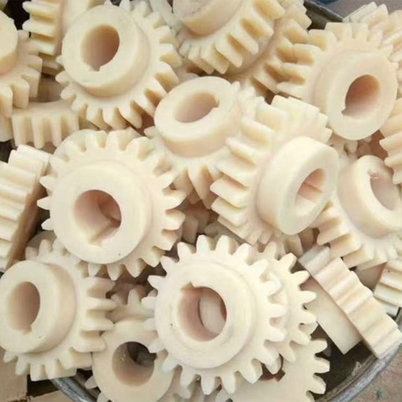
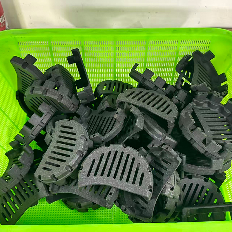
Powder-bed nylon processes build without support structures, which frees the designer to nest complex geometry, internal channels and living hinges that no other route can produce economically. Parts come out with a uniform matte finish and isotropic-enough properties to serve as genuine functional components: brackets, ducts, housings, jigs and end-use covers. Glass-filled and carbon-filled nylon grades raise stiffness and dimensional stability for fixtures that must hold a datum under clamping load. For engineers, the important property is not headline tensile strength but the ability to nest dozens of dissimilar parts into a single build and receive them all in the same four-day window.
Metal additive manufacturing for geometry that cannot be machined
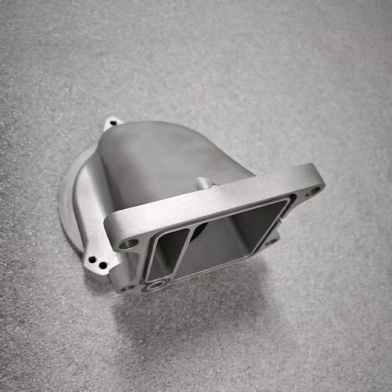
Metal printing earns its place when a part contains conformal cooling channels, internal manifolds, topology-optimised load paths or thin-wall lattices that a cutter simply cannot reach. Aluminium alloys, stainless grades, tool steels and titanium are all routinely processed. The discipline that separates a serious supplier from a casual one is post-processing: correct stress relief before the part leaves the build plate, controlled support removal, hot isostatic pressing where porosity matters, and finish machining of every sealing face, bearing seat and threaded hole. A metal print that has not been finish machined should never be treated as a precision component.
Matching Process to Requirement: A Comparison Table
The table below summarises the practical envelope of each route as it is normally supplied by an industrial 3D printing service that also operates machining and molding lines. Tolerances are stated as typically achievable on well-designed geometry, not as absolute limits, and they assume the part has been reviewed for manufacturability before the job is released.
| Process route | Typical tolerance | As-built surface | Material family | Economic batch |
|---|---|---|---|---|
| Resin SLA | ±0.1 mm | Ra 3–6 µm | Standard and engineering resin | 1–20 |
| Nylon powder bed | ±0.2 mm | Ra 10–15 µm | PA12, PA11, filled nylon | 1–500 |
| Metal laser powder bed | ±0.2 mm | Ra 8–20 µm | Aluminium, stainless, tool steel, titanium | 1–100 |
| 3-axis CNC machining | ±0.02 mm | Ra 1.6–3.2 µm | Aluminium, steel, brass, engineering plastic | 1–2000 |
| 5-axis CNC machining | ±0.01 mm | Ra 0.8–1.6 µm | Aluminium, stainless, titanium, superalloy | 1–2000 |
| Silicone mold replication | ±0.15 mm | Mirrors the master | PU resins simulating ABS, PP, rubber | 20–200 |
Read the table by column rather than by row. The tolerance column shows why finish machining after printing is not optional for precision features: the best additive tolerance on the list is still an order of magnitude looser than routine 5-axis machining. The surface column explains why painted cosmetic parts almost always start as resin masters or machined blanks rather than nylon prints. The batch column is the one buyers most often ignore, and it is the one that determines whether a program stays profitable as volumes grow.
Large Scale 3D Printing Service: Building Beyond the Standard Envelope
Demand for a large 3d printing service has grown faster than machine build volumes have, and the practical answer for oversized geometry is rarely a single enormous machine. It is intelligent sectioning: splitting the model along planes chosen for structural and cosmetic reasons, printing the segments in parallel, and bonding or mechanically joining them with located features designed into the split. Done well, a sectioned part is stronger and straighter than a single-piece print of the same size, because each segment experiences less thermal gradient during the build.
The chart below compares the longest single dimension routinely achievable on each route before sectioning becomes necessary. It is a capability map, not a ranking, and it shows why a large scale 3d printing service and a machining department are natural partners rather than competitors.
This chart repays careful reading for anyone specifying oversized parts. Large-format extrusion reaches the greatest single-piece dimension of any additive route shown, which is why it dominates applications such as check fixtures, forming tools, mock-up enclosures and foundry patterns where dimensional tolerance in the tenths of a millimetre is acceptable. Gantry milling reaches almost as far while holding tolerances roughly twenty times tighter, so the two processes are frequently paired: print the bulk shape, then machine the datums and mating faces on the same platform. Metal powder-bed systems sit at the low end of the size axis, which is the single biggest constraint on metal additive adoption and the reason large metal assemblies are usually printed as segments and joined. Nylon and industrial resin occupy the middle band, comfortably covering most consumer-product housings and automotive interior components in one piece. The practical conclusion is that build envelope should be treated as a design input from the first CAD session, not as a constraint discovered at quotation.
Custom CNC Machining Services: Where Precision Is Actually Created
Additive manufacturing creates geometry; machining creates precision. Any China CNC Machining OEM Supplier worth engaging should be able to explain, unprompted, how they hold position between operations, how they compensate for tool wear across a batch, and how they verify the first article before releasing the rest. Those three answers reveal more about real capability than a list of machine brands ever will.
Aluminium machining service considerations
Aluminium remains the workhorse of prototype and low-volume production because it cuts quickly, holds tolerance well and accepts a wide range of finishes. An effective aluminium cnc service pays attention to three details that separate acceptable parts from excellent ones: chip evacuation in deep pockets, where recutting chips leaves witness marks; wall thickness relative to clamping force, because thin walls deflect and then spring back out of tolerance; and the correct choice between 6061, 7075 and 5052 depending on whether the priority is machinability, strength or formability. A well-planned aluminium part can move from raw stock to finished component in a single setup on a 5-axis machine, eliminating the stack-up error that three separate setups would introduce.
Stainless steel and harder metal cnc services
Stainless steel cnc machining services demand a different mindset. Work hardening means that a tool which dwells or rubs instead of cutting will create a hardened layer that destroys the next pass. Heat management, rigid fixturing, sharper tool geometry and deliberate feed strategies all matter more than raw spindle speed. For 316 and duplex grades the cycle time can be two to three times that of an equivalent aluminium part, which is why honest lead times from a stainless supplier are longer, and why a quotation that ignores the difference should be questioned.
Why 5 axis cnc machining services change the design conversation
Simultaneous five-axis work allows the cutter to approach the workpiece from continuously varying angles. The engineering benefits are concrete: shorter, more rigid tools reach deep features without chatter; undercuts and compound angles are machined without custom fixtures; and, most importantly, features that must be concentric to each other are cut in one setup so their relationship is defined by the machine rather than by an operator's re-clamping. For complex housings, impellers, manifolds and medical instruments, this is the difference between a part that assembles and a part that almost assembles.
Comparing the Three Core Routes on the Criteria That Matter
Engineers rarely choose a process on a single axis. The radar chart below scores the three core routes offered by a full-service platform across six criteria that consistently appear in sourcing decisions, on a scale of one to five. It is intended as a decision aid for the first conversation of a project, when the process has not yet been fixed.
The shapes tell a clearer story than the individual scores. 3D printing forms a tall, narrow profile that peaks on geometric freedom and single-piece speed while falling away on tolerance and finish, which is exactly the signature of a process used for early iteration and for shapes that cannot be cut. CNC machining forms a broad, balanced profile with its strongest points on tolerance, material range and finish, confirming its role as the route that turns a concept into a qualified component. Silicone mold replication sits between the two, trading a little accuracy for the ability to produce dozens of identical cosmetic parts from one master. Crucially, the three polygons overlap rather than nest, meaning no single process dominates, and the correct answer for most real programs is a sequence rather than a choice. The practical implication is that a supplier offering only one of these three shapes can serve only one phase of a product's life, while an integrated platform can carry the same part from concept model to pilot batch without changing vendors.
Silicone Mold Replication: The Bridge Between Prototype and Production
Between one-off printing and hard steel tooling lies a gap that catches many programs by surprise. A team needs fifty or a hundred parts for a field trial, a certification submission or a trade launch, but the volume cannot justify a production mold and the timeline cannot absorb tooling lead time. Silicone mold replication, also called vacuum casting or urethane casting, fills that gap precisely.
The workflow is straightforward. A master pattern is produced, typically by high-resolution resin printing or by machining, and finished to the exact surface the final part requires because the silicone will faithfully copy every detail, including flaws. The master is suspended in a frame and encased in liquid silicone, which is cured and then cut open along a carefully planned parting line. Polyurethane resins selected to simulate ABS, polypropylene, rubber, glass-filled nylon or transparent acrylic are then poured under vacuum into the cavity. A single mold typically yields between 20 and 25 quality copies before dimensional drift requires a fresh tool, so a hundred-piece order is planned around four or five molds running in parallel.
The chart below plots average production hours per finished part as batch size grows, which is the clearest way to see where each route earns its place.
Five observations follow from these curves. At a batch of one, silicone molding is by far the least efficient route because the entire mold-making effort is charged to a single piece, which is why nobody casts a one-off. By ten pieces the silicone curve has collapsed dramatically and already sits close to the other two, showing how quickly mold amortisation works in a buyer's favour. Beyond fifty pieces all three curves flatten, meaning that incremental volume no longer changes the per-part effort much and the decision shifts to material properties and tolerance instead. The 3D printing curve is the flattest across the whole range, which is its quiet advantage: it is predictable at any quantity, with no tooling step to plan around. The CNC curve continues to decline gently past two hundred pieces because programming and fixturing are one-time efforts spread across a growing run, which is why custom cnc machining services often become the most efficient route at exactly the volumes where prototyping methods stop scaling.
Surface Treatment: The Step That Determines Perceived Quality
A dimensionally perfect part with an inconsistent finish will be judged a failure by everyone who is not holding a caliper. Surface treatment is therefore not cosmetic decoration; it is the stage where engineering work becomes visible, and it should be specified with the same rigour as a tolerance callout.
The main treatments available within a one-stop platform, and what each one is actually for, are set out below.
- Sanding and polishing, which removes layer lines from printed parts and prepares any surface for paint or plating.
- Bead and sand blasting, which produces a uniform matte texture that hides minor tool marks and gives coatings a mechanical key.
- Spray painting in gloss, satin, matte, soft-touch and textured systems, matched to a supplied colour reference rather than to a verbal description.
- Anodising for aluminium, which adds a controlled oxide layer for corrosion resistance and colour without meaningful dimensional change.
- Powder coating for steel and aluminium parts that need a thick, impact-resistant film.
- Electroplating and vacuum metallising for reflective and decorative surfaces on both metal and plastic substrates.
- Silk screen printing, pad printing and laser marking for logos, legends and traceability codes.
Two disciplines separate good finishing from mediocre finishing. The first is masking: threads, bearing bores, sealing faces and electrical contact areas must be protected so that film build does not consume the tolerance the machinist worked to achieve. A typical paint system adds 30 to 60 microns per surface, which is enough to turn a comfortable sliding fit into an interference fit if it is applied to an unmasked bore. The second is colour control under standardised lighting, because a colour approved under workshop fluorescents will not match under showroom lighting, and rework at that stage is painful for everyone.
What Work Actually Arrives at a One-Stop Platform
Understanding the typical mix of projects handled by an established supplier helps a buyer judge whether their own requirement is routine or exceptional for that shop. The distribution below reflects a representative pattern of incoming work across industrial customers.
This distribution carries several lessons for buyers. Functional prototyping remains the largest single category, confirming that most parts leaving a modern platform are intended to be tested rather than merely looked at, and therefore must be built from materials with meaningful mechanical data. Low-volume end-use parts form the second largest block, and their growth is the clearest evidence that additive and bridge processes have moved out of the model shop and into real production. Design validation models still account for roughly a fifth of intake, which reflects how much value teams continue to place on holding a physical object during a review. Tooling and mold masters are a smaller but technically demanding share, because master patterns must be finished to the standard of the final part before replication begins. Aftermarket and spare parts represent the fastest-growing segment in many sectors, since digital inventory removes the need to warehouse slow-moving components, and a supplier who retains validated process files can reproduce a discontinued part years after the original run.
How to Evaluate a China 3D Printing Services Factory Before You Commit
Choosing among 3d printing service providers and machining suppliers is a structured exercise, not an instinctive one. The sequence below reflects the order in which the questions actually matter, and it is worth working through it before the first order rather than after the first problem.
- Confirm process breadth. Ask whether resin, nylon, metal, machining, casting and finishing are performed in-house or subcontracted, and request the answer process by process.
- Request a design-for-manufacturing review on your actual file. The quality of the feedback, not its speed, reveals engineering depth.
- Establish inspection practice. Ask what is measured, with what equipment, at what frequency, and what report accompanies the shipment.
- Clarify material traceability. Certificates should name the specific lot used for your parts, not the grade in general.
- Test communication with a technical question that has no simple answer, and observe whether you receive an engineer's reply or a sales reply.
- Verify intellectual property handling, including confidentiality terms, file storage practice and whether your geometry is ever used as a demonstration sample.
- Run a paid pilot on a genuine part before transferring a program, and evaluate the pilot on documentation as well as on the parts themselves.
Two warning signs deserve particular attention. A supplier who accepts every requirement without a single question about tolerance intent, datum selection or functional surfaces has probably not opened the file. And a supplier who quotes an identical lead time for resin, nylon, metal and machined stainless parts is quoting from a template rather than from capacity. The most reliable predictor of a successful long-term relationship is the quality of the questions asked before the first part is made.
The Design-to-Product Workflow on a Single Platform
The value of an integrated smart manufacturing platform is easiest to see when the whole route is drawn as one continuous chain rather than as a series of purchase orders. The diagram below maps the seven stages a typical part passes through from first conversation to packed shipment.
Each stage in this chain exists to protect the one after it. Design intake and manufacturability review catch geometry problems while they are still cheap to fix in CAD, and this is where the majority of avoidable delays are prevented. Digital process planning fixes the setups, fixtures and toolpaths before any material is consumed, so that the shop floor executes a plan rather than improvising. Material and route selection is the decision point where the earlier comparison charts are actually applied to a specific part. The manufacturing block is drawn as a single unit deliberately, because printing and machining are frequently applied to the same component rather than being alternatives. The lower row shows the finishing chain, where silicone replication multiplies a validated part into a batch, surface treatment gives it its final identity, and inspection closes the loop by comparing the physical result against the original intent, so that nothing ships without evidence that it matches the model it came from.
About Zhejiang Jiaheng Intelligent Equipment Manufacturing Co., Ltd.
Zhejiang Jiaheng Intelligent Equipment Manufacturing Co., Ltd. is a pioneer in industrial innovation and manufacturing. Our expert design team turns client ideas into practical, aesthetic product designs. We offer 3D printing in resin, nylon, metal, and other materials, and have advanced machining. Silicone mold replication allows for low-cost, high-precision small-batch production. Surface treatments like painting enhance product appearance. With our one-stop service, clients can finish the design-to-product process on one platform, saving time and cost. We aim to be a reliable long-term partner for industrial development.
In practice, that structure means a client can arrive with a sketch, a functional requirement or a legacy component that no longer has drawings, and leave with inspected, finished parts without ever managing a second supplier. The design team translates intent into manufacturable geometry, the additive and machining departments produce it, the replication line multiplies it when a batch is required, and the finishing department delivers it in the condition the end market expects. Every stage shares the same part number, the same tolerance record and the same point of contact.
Industry Applications and Where Each Route Fits
Automotive and mobility
Development programs rely on printed interior trim for fit studies, nylon ducts and brackets for underhood packaging trials, and machined aluminium housings for powertrain and battery test rigs. Motorsport and specialist vehicle builders use the same combination for genuinely low-volume end-use parts, where hard tooling would never be justified.
Medical devices and laboratory equipment
Instrument housings, surgical guides, handpiece bodies and fluid manifolds benefit from the combination of complex printed geometry and machined sealing surfaces. Stainless steel cnc machining services are frequently specified here for components that must be repeatedly sterilised, and traceable material documentation is not negotiable.
Consumer electronics and appliances
Appearance models built from resin masters and painted to a colour standard drive design reviews, while cast urethane batches supply pilot builds and certification samples. Machined aluminium mid-frames and heat spreaders appear in the same programs, which is why a commercial 3d printing service that also machines is so much more useful than one that does not.
Industrial automation and robotics
End-of-arm tooling, custom grippers, sensor mounts and guarding are classic candidates for a cnc machining prototype service backed by additive capability. Requirements change as a production line is commissioned, so the ability to revise a fixture and receive the new version within days is worth more than a marginal improvement in any single process.
Preparing Files and Specifications That Get Good Parts Back
Suppliers can only work with what they receive, and a surprising share of quality disputes originate in incomplete information rather than in manufacturing error. Sending a parametric file such as STEP alongside any mesh export allows the supplier to rebuild toolpaths accurately, because a mesh discards the mathematical definition of a curved surface and forces the machinist to approximate it.
Tolerances should be applied selectively. Marking every dimension as critical tells the supplier nothing and forces them to treat the loosest feature with the same care as the tightest. Identifying the three to five features that truly control function lets the whole process plan be organised around protecting them. Datum selection deserves the same thought: the datum scheme should reflect how the part is located in its assembly, so that the inspection report answers the question the design actually cares about.
Finally, state the intended use. A supplier who knows a bracket will see vibration at elevated temperature will steer the material choice differently than one who assumes it is a display model. That single sentence of context frequently prevents an entire iteration loop, and it costs nothing to include in the first message.
Frequently Asked Questions
Q1: How do I decide between 3D printing services and CNC machining for a new part?
Start with tolerance and geometry. If the part contains internal channels, lattices or organic shapes that a cutting tool cannot reach, additive manufacturing is the natural route. If the part needs features held to ±0.05 mm or tighter, needs a specific certified alloy, or needs a fine machined surface finish, machining is the answer. Many real components need both, with the bulk shape printed and the critical faces machined afterwards, and a supplier operating both capabilities can plan that sequence in one process document rather than across two purchase orders.
Q2: What file formats and information should I send with a request?
Send a STEP or IGES file as the geometric master, plus a 2D drawing showing critical dimensions, datums, surface finish requirements and material specification. Include the quantity, the intended application and any regulatory context. If colour or texture matters, supply a physical reference or a recognised colour code rather than a description in words. Where a mesh format such as STL is used for a purely additive job, confirm the export resolution, since a coarse mesh will show visible faceting on curved surfaces.
Q3: Can printed parts be used as real production components, or only as prototypes?
They can be genuine production components when the material and process are chosen deliberately. Nylon powder-bed parts, particularly filled grades, serve as end-use brackets, housings, ducts and fixtures in many industries. Metal printed parts are used in production where the geometry cannot be produced any other way, provided they are correctly stress relieved and finish machined on functional surfaces. The practical limits are surface finish, achievable tolerance without secondary machining, and long-term behaviour under ultraviolet exposure or sustained heat, all of which should be confirmed against the specific material datasheet.
Q4: How many parts can one silicone mold produce before quality declines?
A typical mold yields around 20 to 25 acceptable copies, though the exact figure depends on part geometry, undercuts and the casting resin used. Aggressive undercuts and sharp internal corners wear the silicone faster. For larger requirements, multiple identical molds are produced from the same master and run in parallel, which preserves consistency across the batch and shortens the overall schedule. Because every mold is taken from one master, dimensional agreement between molds is generally very close.
Q5: What tolerances are realistically achievable on machined aluminium and stainless steel parts?
Routine 3-axis work holds ±0.02 mm on well-supported features, and simultaneous 5-axis work holds ±0.01 mm on parts designed for single-setup machining. Achieving those figures depends on wall thickness, part length, clamping strategy and thermal stability during the cut. Long thin features and deep pockets will always be looser than compact solid ones. The most productive approach is to specify tight tolerances only where function requires them and to discuss those specific features with the supplier before the process plan is fixed.
Q6: How is confidentiality handled for proprietary designs?
A confidentiality agreement should be executed before files are transferred, and it should cover file storage, internal access, subcontractor disclosure and the disposal of masters, fixtures and residual material after a project closes. Ask specifically whether your geometry could ever appear in marketing samples or capability displays, and record the answer in writing. A supplier accustomed to working with development programs will already have a defined process for this and will be able to describe it without hesitation.
related products
-
 Standard FDM Materials 3D Printing Service (PLA, PETG, ABS)
-
 Yellow ABS-Like Resin 3D Printing Service
-
 Aluminum Alloy AlSi10Mg 3D Printing Service
-
 Decal & Silk Screen Printing
-
 PAHT+CF High-Temp Nylon Carbon Fiber Reinforced Material 3D Printing Service
-
 PPS+CF Carbon Fiber Reinforced Material 3D Printing Service
Contact Information
-

zjjh@jiahzn.cn
-

+86-18936159957
-
+86-18966326325
ADD
-

Building 7, No. 188, Hongni Section of Zha Wang Road, Danghu Subdistrict, Pinghu City, Jiaxing City, Zhejiang Province, China
Copyright © 2026 by Zhejiang Jiaheng Intelligent Equipment Manufacturing Co., Ltd. OEM/ODM Integrated Smart Manufacturing Platform Manufacturers
