- 3D Printing Services

- CNC Machining Services

- Vacuum Casting Services

- Surface Finishing Services







 English
 Español

China FDM 3D Printing, CNC Milling, Turning and Vacuum Casting Guide
Content
- 1 The Direct Answer: Choosing Between FDM, CNC and Vacuum Casting
- 2 FDM Plastic 3D Printing: Fast, Economical Geometry for Iteration
- 3 CNC Milling: The Standard for Prismatic Precision Parts
- 4 CNC Turning: The Right Process for Rotational Geometry
- 5 Milling and Turning Side by Side
- 6 Precision CNC Milling: Holding Tolerance That Actually Matters
- 7 Comparing Lead Time Across FDM, Milling, Turning and Casting
- 8 Vacuum Casting and Polyurethane Resins: Multiplying a Validated Part
- 9 Cost-Efficiency Across Batch Sizes: A Column Chart View
- 10 Capability Comparison Across All Four Routes
- 11 About Zhejiang Jiaheng Intelligent Equipment Manufacturing Co., Ltd.
- 12 Preparing a Part for Milling, Turning or Casting
- 13 Frequently Asked Questions
The Direct Answer: Choosing Between FDM, CNC and Vacuum Casting
If you are comparing an fdm 3d printing service against CNC milling, CNC turning or vacuum casting for an upcoming part, the decision comes down to three factors: how quickly you need a physical object, how tight the tolerance actually needs to be, and whether the geometry is rotational, prismatic, or organic. FDM plastic printing is the fastest and most economical way to hold a shape in your hand within a day, CNC milling is the right tool for prismatic parts with flat faces, pockets and holes that demand real tolerance, CNC turning is unmatched for cylindrical and rotationally symmetric components, and vacuum casting is the correct choice the moment a validated master needs to become twenty or more identical copies. None of these four routes replaces the others; each covers a distinct geometry and volume window, and the four together cover almost every part a mechanical design will ever produce.
A short rule of thumb: reach for plastic 3d printing service capability when the part is complex, low volume and forgiving on tolerance; reach for a CNC milling service factory when flat faces, pockets, slots or precise holes define the part; reach for a cnc turning company when the part is a shaft, bushing, spindle or any other cylindrical form; and reach for a Custom Vacuum Casting Manufacturer once a single approved sample must become a batch of consistent, paintable, functional parts. A China Custom Precision CNC Milling Factory that also operates FDM and vacuum casting under one roof lets a single part move through whichever combination of these routes it actually needs, without a change of vendor at each stage.
The sections below explain each process in working detail, compare them against real tolerance and cost data, and walk through how vacuum casting and compression molded silicone parts extend that same platform into small-batch production.
FDM Plastic 3D Printing: Fast, Economical Geometry for Iteration
Fused Deposition Modeling builds parts by extruding molten thermoplastic filament layer by layer through a heated nozzle. It is the most widely deployed additive process in the world for a simple reason: the equipment is reliable, the material range is broad, and a China FDM Plastic 3D Printing Service Factory can turn a design file into a physical part faster than almost any other manufacturing route. This makes fdm printing service the default choice for early concept models, jigs, fixtures, enclosure mockups and any part where the goal is to check fit and form rather than certify final mechanical performance.
Material choices that matter
A China Custom FDM Plastic 3D Printing Manufacturer typically stocks ABS for general-purpose toughness, PLA for dimensionally stable low-cost models, PETG for a balance of strength and moisture resistance, and engineering filaments such as nylon, polycarbonate and carbon-fiber-filled composites for parts that need to survive real handling and mechanical load. Layer adhesion is directional, meaning FDM parts are noticeably stronger when loaded in the plane of each layer than when loaded across layer boundaries, so a competent China FDM Plastic Prototype 3D Printing Supplier will orient a part deliberately around its expected load path rather than printing it in whatever position uses the least material.
The as-built surface shows visible layer lines at typical resolutions between 0.1 mm and 0.3 mm, coarser than resin processes but entirely acceptable for functional prototypes, internal components and parts destined for painting after sanding. For applications where visible texture is unacceptable, plastic printing services generally recommend a resin or nylon powder process instead, reserving FDM for its real strengths: speed, low cost per part at low volume, and a very wide range of accessible engineering materials.
CNC Milling: The Standard for Prismatic Precision Parts
CNC milling removes material from a solid block using rotating cutting tools guided along programmed paths, and it remains the primary route for parts defined by flat faces, pockets, slots, precise holes and mounting features. A CNC Milling Service Manufacturer in China works from aluminium, steel, stainless steel, brass, titanium and a range of engineering plastics, and the process scales from a single prototype cnc milling job to production runs of thousands of identical parts.
Three-axis versus multi-axis milling
Standard three-axis milling handles the majority of prismatic geometry efficiently and is the backbone of any custom cnc milling operation. Parts with features on multiple faces, however, require repositioning between operations unless the shop has four- or five-axis capability, and every repositioning introduces a small opportunity for stack-up error. A metal cnc milling department equipped with multi-axis machines can hold features on several faces to a single coordinate system in one setup, which materially improves the relationship between those features compared with a part that was flipped and re-clamped twice.
Where large cnc milling changes the conversation
For oversized plates, structural brackets and base frames, large cnc milling depends on gantry-style machines with extended travel rather than standard vertical machining centers. Thermal stability becomes the dominant concern on large parts, since a temperature swing across a meter-scale aluminium plate can move a feature measurably out of tolerance before the part ever leaves the machine, which is why serious large-format shops machine in temperature-controlled environments and allow stock to normalise before final cuts.
CNC Turning: The Right Process for Rotational Geometry
CNC turning rotates a workpiece against a stationary or moving cutting tool, making it the natural process for any part that is fundamentally cylindrical: shafts, bushings, spindles, pins, rollers and threaded fittings. A China CNC Turning Service Factory typically holds tolerances tighter and finishes surfaces more consistently on rotational parts than milling ever could, because the continuous rotation produces a naturally uniform surface rather than a series of discrete tool passes.
Live tooling and combined operations
Modern turning centers equipped with live tooling can mill flats, drill cross-holes and cut keyways without transferring the part to a separate milling machine, which is precisely how a cnc turning company reduces the number of setups a complex rotational part requires. This matters because cnc precision turning depends heavily on maintaining a single, unbroken reference from the raw bar stock through to the finished part; every additional transfer between machines is another chance for concentricity to drift.
A China CNC Turning OEM Supplier producing high volumes of a single rotational part, such as a bushing or a shoulder screw, typically runs the job on a CNC lathe with bar feeding, allowing continuous unattended production once the program is validated. A China CNC Turning ODM Manufacturer developing a new rotational component from a client concept, by contrast, will spend proportionally more time on first-article verification before committing to that continuous run.
Milling and Turning Side by Side
The table below summarises where milling and turning naturally apply, to help a design team route a part to the correct process before a quotation is requested.
| Attribute | CNC milling | CNC turning |
|---|---|---|
| Best-fit geometry | Prismatic blocks, plates, housings | Shafts, bushings, rotational parts |
| Typical tolerance | ±0.02 mm | ±0.01 mm on diameter |
| Surface finish | Ra 1.6–3.2 µm | Ra 0.8–1.6 µm |
| Typical setups for a complex part | 2–4 (or 1 with 5-axis) | 1–2 with live tooling |
| Material utilisation | Moderate, block stock | High, bar stock |
The table clarifies a point many first-time buyers miss: turning generally holds tighter diametral tolerance than milling holds on an equivalent linear dimension, because a rotating workpiece against a fixed tool removes the positioning error that comes from moving a cutter across multiple axes. Milling, in exchange, offers geometric freedom that turning simply cannot: pockets, non-cylindrical bosses and multi-face feature sets are milling's natural territory. A part that combines a cylindrical body with flat mounting features, such as a machined bracket with a shaft on one end, is often routed through both processes in sequence, turned first for the rotational body and then milled for the flats, holes and keyways that finish the part.
Precision CNC Milling: Holding Tolerance That Actually Matters
The word precision is used loosely across the industry, so it is worth defining concretely. A China Precision CNC Machining Manufacturer offering high precision cnc milling should be able to state, without hesitation, what tolerance their equipment holds on a specific feature type, under what inspection method, and at what confidence level. Precision CNC Milling Service claims that cannot be backed by a measurement report and a calibrated instrument are not claims worth relying on for a critical assembly.
What actually drives precision on a milled part
Four factors dominate real-world precision milling outcomes: machine rigidity and thermal stability, fixture design that eliminates part movement under cutting load, tool selection matched to the material and feature depth, and in-process measurement that catches drift before an entire batch is affected. A part machined in a single setup on a rigid 5-axis platform will consistently outperform the same part machined across four separate setups on a basic 3-axis machine, even when both machines are nominally capable of the same positioning accuracy, because every re-fixturing event reintroduces alignment uncertainty.
Where cnc prototyping services fit into the precision conversation
Precision does not only apply to production runs. cnc prototyping services exist specifically to validate that a design's tightest features can actually be held before committing to a full batch. A single precision-machined prototype, measured against the drawing with a coordinate measuring machine, tells a design team more about manufacturability than any amount of simulation, and it is far cheaper to discover a tolerance problem on one part than on five hundred.
Comparing Lead Time Across FDM, Milling, Turning and Casting
The horizontal bar chart below compares typical elapsed lead time, from a released file to packed parts, across the four processes covered so far, for a moderately complex part at a batch size of twenty pieces.
Reading this chart alongside the earlier process descriptions clarifies a common misconception: at a batch of twenty pieces, vacuum casting is not automatically the fastest option, because building the mold itself consumes several days before any casting can begin. FDM plastic printing remains the fastest route at this batch size specifically because twenty parts can often be nested and printed together in a single build cycle, particularly for smaller components. CNC turning finishes ahead of milling at this batch size for parts genuinely suited to a lathe, reflecting the efficiency of bar-fed continuous production once the first part is validated. CNC milling sits in the middle, its exact position depending heavily on how many setups the specific geometry requires. The vacuum casting figure should not be read as a weakness of the process; rather, it reflects that the seven days include mold construction, and that time investment pays off precisely when the batch grows well beyond twenty pieces, which the earlier crossover analysis in this series has already shown.
Vacuum Casting and Polyurethane Resins: Multiplying a Validated Part
Once a design has been validated, either as a machined prototype or a printed master, a China Custom Vacuum Casting Manufacturer can turn that single approved sample into a consistent batch without the cost or lead time of hard tooling. The process begins with a master pattern, most often a precision-machined or resin-printed part finished to the exact surface the production part requires, since the silicone mold will faithfully reproduce every detail of that master, including any imperfection.
Why polyurethane resin selection matters
A China Silicone Mold Vacuum Casting Manufacturer stocks a range of polyurethane resins engineered to simulate specific production plastics: rigid ABS-like grades for enclosures, flexible rubber-like grades for gaskets and grips, glass-filled grades for stiffness, and transparent grades for light pipes and lenses. Polyurethane vacuum casting can also embed features that would be difficult in a molded production part, such as multiple durometers cast into a single component through sequential pours, or metal inserts positioned in the mold before the resin is introduced.
Compression molded silicone parts as a complementary route
Where a part is genuinely a silicone rubber component rather than a rigid plastic simulation, a China Custom Compression Molded Silicone Parts Manufacturer uses a different process entirely: raw silicone rubber is placed into a heated metal mold cavity and cured under pressure, producing gaskets, seals, keypads, grips and other elastomeric parts with the material properties of true silicone rather than a resin that merely resembles a plastic. This route is typically selected when the part must flex repeatedly in service, resist a wide temperature range, or provide a genuine elastomeric seal, applications where a polyurethane vacuum casting simulation would not hold up over time.
Cost-Efficiency Across Batch Sizes: A Column Chart View
The column chart below indexes relative per-part effort for FDM, CNC machining and vacuum casting at five batch sizes, using an index scale where lower is more efficient, to show how the most efficient route shifts as volume grows.
This column chart makes the crossover pattern concrete rather than abstract. At a single piece, FDM is clearly the most efficient route because it requires no programming, no fixturing and no tooling investment at all. By ten pieces the three routes have already converged noticeably, with vacuum casting closing much of the gap as its mold cost begins to spread across more parts. At thirty pieces the three columns sit close together, marking the transition zone where the correct choice depends more on tolerance and material requirements than on raw efficiency. By a hundred pieces vacuum casting has become distinctly less efficient than either FDM or CNC for this particular part profile, a reminder that the crossover point shifts with part size and complexity rather than following one universal number. At three hundred pieces, CNC machining and FDM remain viable while vacuum casting for this profile would typically have been replaced by a production tooling conversation, which lies outside the scope of the four processes compared here.
Capability Comparison Across All Four Routes
The radar chart below scores FDM plastic printing, CNC milling, CNC turning and vacuum casting across five criteria that recur constantly in real sourcing conversations, on a scale of one to five.
The four overlapping shapes tell a coherent story once read side by side. FDM stretches furthest toward single-piece speed and geometric freedom, confirming its role as the fastest way to hold a complex shape without any tooling. CNC turning stretches distinctly toward tolerance control, reflecting its natural advantage on diametral precision for rotational features, while contracting on geometric freedom because it is fundamentally limited to shapes producible by rotation. CNC milling occupies a broad, balanced footprint across tolerance, surface finish and material range, which is exactly why it remains the default choice for general precision components. Vacuum casting pulls strongly toward batch scalability and surface finish while pulling back sharply on single-piece speed, matching its identity as a multiplication process built on top of an already-validated part. The absence of any single dominant shape on this chart is the central lesson of the whole comparison: a design that starts as an FDM concept model, moves through CNC milling or turning for functional validation, and finishes as a vacuum-cast batch has simply followed the natural path that each process was built for.
About Zhejiang Jiaheng Intelligent Equipment Manufacturing Co., Ltd.
Zhejiang Jiaheng Intelligent Equipment Manufacturing Co., Ltd. is a pioneer in industrial innovation and manufacturing. Our expert design team turns client ideas into practical, aesthetic product designs. We offer 3D printing in resin, nylon, metal, and other materials, and have advanced machining. Silicone mold replication allows for low-cost, high-precision small-batch production. Surface treatments like painting enhance product appearance. With our one-stop service, clients can finish the design-to-product process on one platform, saving time and cost. We aim to be a reliable long-term partner for industrial development.
Within that structure, FDM plastic printing supports the earliest concept iterations, precision CNC milling and turning validate and produce functional metal and plastic components, vacuum casting and compression molded silicone parts extend a validated design into a consistent small batch, and surface finishing delivers every part in the condition its intended application requires. Every stage runs on the same part file and the same engineering point of contact, which is what actually distinguishes a one-stop platform from a collection of separately managed vendors.
Preparing a Part for Milling, Turning or Casting
A well-prepared file shortens quoting time and reduces the risk of a misinterpreted requirement. The list below covers the details that most directly affect whether a milled, turned or cast part comes back exactly as intended.
- Provide a native or STEP file rather than a mesh export whenever a precision feature is involved.
- Call out the two or three features that genuinely control fit or function, rather than marking every dimension as critical.
- State the datum scheme the part will use in its final assembly.
- Specify material grade precisely, since 6061 and 7075 aluminium, or 303 and 316 stainless, behave very differently under the same toolpath.
- Indicate quantity now and expected quantity over the following months, since this changes whether milling, turning or vacuum casting is the more efficient route.
A supplier who receives this information in the first message can typically return a meaningful quotation and manufacturability comment on the same day, rather than cycling through a series of clarifying questions before the real conversation even starts.
Frequently Asked Questions
Q1: When should I choose FDM printing instead of CNC machining for a prototype?
Choose FDM when the priority is speed and geometric complexity rather than tight tolerance or a specific certified material. FDM excels at internal cavities, organic shapes and rapid design iterations where a part might change three times in a week. Once the design has stabilised and the part needs a specific engineering material, a tight tolerance, or a finished appearance, CNC machining becomes the more appropriate route.
Q2: What is the difference between three-axis and five-axis CNC milling in practice?
Three-axis milling moves the cutting tool along three linear directions and handles most flat and pocketed geometry efficiently, but it requires the part to be repositioned to reach features on other faces. Five-axis milling adds simultaneous rotational movement, allowing the tool to reach compound angles and multiple faces without repositioning the part. The practical benefit is that features machined in one five-axis setup maintain a tighter relationship to each other than the same features machined across several three-axis setups.
Q3: Why is CNC turning generally more precise than milling for cylindrical features?
Turning rotates the workpiece continuously against the cutting tool, which produces a naturally uniform, concentric surface without the discrete tool-path segments that milling a round feature would require. This continuous-cut approach reduces the positioning error that accumulates when a cutter approaches a curved surface from multiple angles, which is why diametral tolerances on turned parts are typically tighter than equivalent milled features.
Q4: How is vacuum casting different from compression molded silicone parts?
Vacuum casting pours polyurethane resin into a silicone mold to simulate the appearance and mechanical behaviour of production plastics such as ABS or polypropylene, and it is chosen when the final part will actually be made from a rigid or semi-rigid plastic. Compression molded silicone parts use genuine silicone rubber cured under heat and pressure in a metal mold, and they are chosen when the part itself needs to be a true elastomer, such as a gasket, seal or grip that must flex repeatedly and resist a wide temperature range.
Q5: How many setups does a typical complex machined part require?
On a standard three-axis machine, a part with features on multiple faces commonly requires two to four separate setups, each involving repositioning and re-referencing the part. On a five-axis machine, many of those same features can be reached in a single setup, which reduces both the elapsed machining time and the accumulated positional error between features. The right number of setups for any given part depends on its specific geometry and should be discussed with the supplier before final quoting.
Q6: What information should I include when requesting a quote for milling or turning?
Include a STEP file, a 2D drawing marking the critical dimensions and their tolerances, the exact material grade required, the desired surface finish, and the quantity needed now along with any expected future volume. Noting the part's operating environment, including temperature exposure and any chemical contact, also helps the supplier confirm the material choice is appropriate before machining begins rather than after the first batch has already been cut.
related products
-
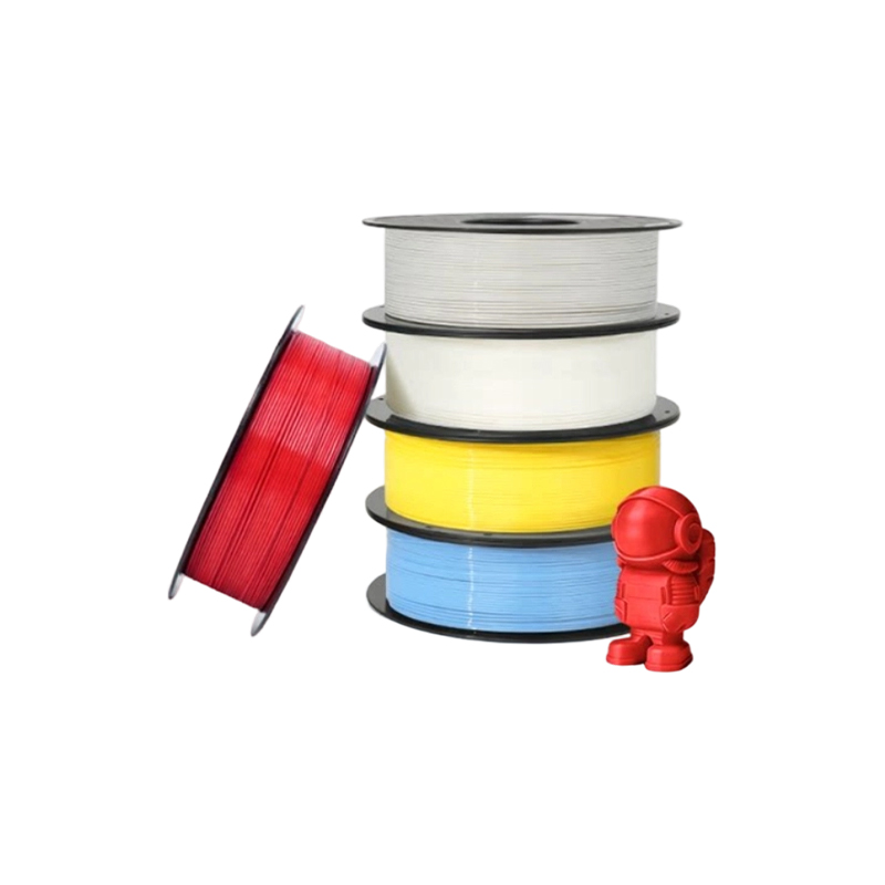 Standard FDM Materials 3D Printing Service (PLA, PETG, ABS)
-
 Aluminum Alloy AlSi10Mg 3D Printing Service
-
 Decal & Silk Screen Printing
-
 PAHT+CF High-Temp Nylon Carbon Fiber Reinforced Material 3D Printing Service
-
 PPS+CF Carbon Fiber Reinforced Material 3D Printing Service
-
 HT-PLA High-Temperature PLA Material 3D Printing Service
Contact Information
-

zjjh@jiahzn.cn
-

+86-18936159957
-
+86-18966326325
ADD
-

Building 7, No. 188, Hongni Section of Zha Wang Road, Danghu Subdistrict, Pinghu City, Jiaxing City, Zhejiang Province, China
Copyright © 2026 by Zhejiang Jiaheng Intelligent Equipment Manufacturing Co., Ltd. OEM/ODM Integrated Smart Manufacturing Platform Manufacturers
